 CoreBrace ( Modeling )
- The CoreBrace icon can be found in the group called ' Model -- Member ' for Ribbon Editor for Modeling . It is available at no additional cost to SDS2 software users whose support accounts are current. For more information, contact your SDS2 sales representative.
| Documentation in progress. |
 |
|
Special indicator :


Red-colored highlighting identifies an entry that is invalid. You need to change that setting, or you will not be able to close this window using " OK ." Tip: If a setting doesn't validate, try hovering it with your mouse and reading the balloon description that appears. It will tell you why the entry is invalid.
To open this window :
- Add a CoreBrace buckling-restrained brace (documentation is on this page)
- Double-click (the brace's steel casing with ' Default ' as the filter)
- Model > Member > Edit (multi-edit is not available for custom members)
- Model > Member > Edit by Piecemark (alternative to Member > Edit )
- Model > Member > Edit by Member Number (alternative to Member > Edit )
- Selection filter (controls selection)
Also see :
- CoreBrace Member Setup ( Home > Project Settings > Job > Plugin Defaults > Member > CoreBrace )
- Add CoreBrace Connection (adds connections to CoreBrace members.)
- corebrace.com (external link to the CoreBrace company website)
Overview :
|
YouTube video: A description of CoreBrace's buckling-restrained brace.
|
|
YouTube video: The workflow between the detailer and the CoreBrace team, and the way that the CoreBrace tool simplifies it, is explained.
|
To add a CoreBrace buckling-restrained brace :
|
YouTube video: CoreBrace member input, and editing are demonstrated.
|
CoreBrace members are placed vertically. It is often easier to place work points for such bracing while in an elevation view . The following instructions assume that you are using a 3-button mouse.
1 . Before adding the buckling-restrained brace(s):
1a : Open the CoreBrace Member Setup window. " Browse " to the location of the CoreBrace-supplied project-specific text file and select it as your " Imported File ."
1b : Open an elevation view . Although you could, possibly, add a CoreBrace member in a plan view by entering Offset Control's "Z+" coordinates to adjust the elevation of your workpoints, it is usually easiest to add a CoreBrace member in an elevation view.
1c : Lay out grid lines or construction lines so that there are points of intersection ( INCL points) wherever you want to place the work points of the brace(s) you are adding. For brace to column with base plate connections, a work point is required at the top of the baseplate of the beam. For brace and beam to column connections, workpoints lie on column baselines and at half the nominal depth of beams. For two point bracing to beam connections, a work point is required along the beam at half of its nominal depth.
1d : Optionally set the icon or set User and Site Options > Modeling > " Automatically process after modeling operation " to a choice that will cause the brace you are adding to automatically have solids created and piecemarks applied when you press " OK " to close the CoreBrace Edit window that opens in step 4.
Tip: Reference the elevation (Z coordinate) reported on the X-Y-Z display while adding the CoreBrace member to ensure that the elevations you place the brace's work points at are correct.
2 . Invoke Add Vertical Brace using any one (1) of the following methods:
▸ Open the Prompt for Member Type window selection list by choosing Model > Member > Add > Prompt for member type . Select CoreBrace from the selection list.
▸ Press F2 . Select CoreBrace from the selection list.
▸ On your ribbon, click the CoreBrace icon, which is pictured above.
▸ Use a keyboard shortcut (if one has been set up).
▸ With Member Mode mouse bindings active, middle-click ( Add ). On the selection dialog that appears, double-click on " CoreBrace ."
3 . The INCL Locate option becomes active along with Locate - Repeat - Return mouse bindings. Do the following to locate the brace's two work points:
|
|
|
bindings |
3a : Place the mouse pointer (
) so that the point location target (
) snaps to the work line of the column or anywhere on the beam you want the lowest point of the buckling-restrained brace to frame to. Left-click ( Locate ).
3b : The status line prompts, "Locate second point:" Reposition the point location target (
4 . The CoreBrace Edit window opens. On it are settings for the buckling-restrained brace whose work points you located in step 3.
Alternative 1 : Edit the settings as desired. Remember to choose the " Member Location " provided by the " Imported file " that matches the member line that you defined in step 3. Then press the " OK " button. Go to step 5.
Alternative 2 : Press the " Cancel " button to close this window and end this operation without creating a buckling-restrained brace member.
Note: The default settings that appear on the CoreBrace Edit window are those of the last CoreBrace member added or edited in this session of Modeling . Even if all you do is double-click such a brace and press " OK " on its edit window, that brace's settings become the defaults for the next-added CoreBrace member. You therefore only have to make changes to those settings which are different for the newly added buckling-restrained brace.
5 . The vertical brace whose settings you entered in step 4, and whose work points you located in step 3, appears in stick form on screen. Locate - Repeat - Return mouse bindings become active. If User and Site Options > Modeling > " Automatically process after modeling operation " is ' Process and create solids ', the new buckling-restrained brace will have automatically undergone all phases of Process and Create Solids . If that option is ' Process ' or ' Do nothing ', you will have to Process > Process and Create Solids in order to have the member piecemarked and able to be displayed in a solid form . Do one (1) of the following:
|
|
|
bindings |
Alternative 1 : Move your mouse pointer (
Alternative 2 : Follow these instructions beginning with step 3 to add a CoreBrace member whose settings or orientation is different than the one you just added.
Alternative 3 : Right-click ( Return ) when you are done adding CoreBrace members.
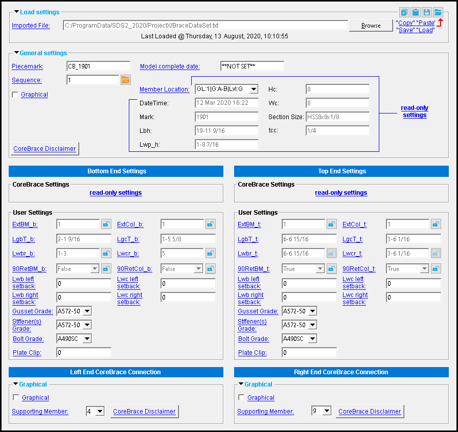
------ Load settings------
Imported file: The file location of the CoreBrace-supplied project-specific text file that instructs the tool how to design the buckling-retrained brace and its connections, including gussets, holes, field bolts, welds, and stiffeners (where required).
To select a connection file: Type in the file path of the report (if you know it), or press the "file cabinet" browse button (
) button to browse for its location.
------ General settings ------
Piecemark : The member piecemark of the CoreBrace buckling-retrained brace. By default, "CB_" is prefixed to such piecemarks.
Typing in characters makes the piecemark a user piecemark .
To clear a user piecemark, or if you are adding a new miscellaneous member, leave this field blank. Piecemarking will assign a system piecemark when you press " OK ."
Sequence : Any sequence name from the Sequence Names setup list can be entered. Either type the sequence, or you can press the "file cabinet" browse button ( ![]() ) and double-click any sequence name that is on the list.
) and double-click any sequence name that is on the list.
Tip: If you want to add a new sequence so that it can be selected here, you should first increase the number of " Maximum sequences " that are available.
Model complete date: **NOT SET** or a month day year (see entering dates ). A model completed date that is set here will be applied unless the buckling-retrained brace is marked for Process or marked for Create Solids .
' **NOT SET** ' indicates that this window is fully editable.
If a ' month day year ' is entered, the affected member is prevented from being altered during the solids creation phase of Process and Create Solids . If you Copy a model-complete member, the " Model complete date " on the new member will be set per User and Site Options > Site > Member status items to copy/repeat . On the context menu, " Edit Other " and " Select Other " can only be used to multi-edit those members under a piecemark that are not model complete members. " Copy " and " Save " buttons on member edit windows remain enabled when a member is model complete.
Operations If event logging for " " for " Members " is turned on (
), the setting of a " Model complete date " is reported as " Model compete date set " in the "
Log " of the affected member. The "
Graphical : ![]() or
or ![]() .
.
A CoreBrace buckling-retrained brace is automatically set to "
Note: The setting to this option does not affect the left or right end CoreBrace connections, which have their own " Graphical " options.
Member Location: None , or a member location provided by the " Imported file ."
Choosing None means that the brace designed will not be project-specific buckling-retrained brace, nor will gussets, welds, and field bolts for brace connections be designed for it.
Choosing a member location selects the project-specific brace and brace connections designed for it. The location described in the following format:
CoreBrace Disclaimer: Pressing this button opens a dialog box bearing the CoreBrace tool's disclaimer.
Read-only: " DateTime ," " Mark ," " LbH ," etc. These are read-only fields whose values are provided by the " Imported file ."
|
|
Naming conventions for CoreBrace settings :
| abbreviation | location | example |
| _b suffix | bottom (left end) connection | LgcT _b |
| _t suffix | top (right end) top connection | LgbT _t |
| b or BM prefix | framing to beam | Lg b T_t |
| c or Col prefix | framing to column | Lg c T_b |
------ Core Brace Settings ------
Read-only: " ni_b ," " no_b ," " eperp_b ," " Lwb_b ," " Lwc_b ," etc. These are read-only fields whose values are provided by the " Imported file ."
------ User Settings ------
To change a setting, first set it to locked ( ![]() ). Validation may not accept your entry if, for example, it exceeds a minimum set by the " Imported file ." Related settings that are unlocked (
). Validation may not accept your entry if, for example, it exceeds a minimum set by the " Imported file ." Related settings that are unlocked ( ![]() ) may be updated.
) may be updated.
Note: If a CoreBrace member's required weld length is greater than the column base plate to which it is welded, not only is the weld not created, but the base plate is not updated in the 3D model. This is intentional: the clash detection provided by the model alerts you that there is a discrepancy between the brace design and that further coordination may be required between the detailer and the CoreBrace company.
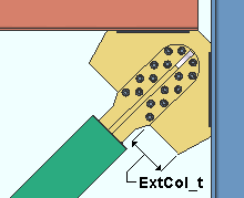
ExtBM_b and ExtBM_t: The distance (in the primary dimension " Units " or other units ), perpendicular to the member line of the CoreBrace member, from an edge of the CoreBrace member to the non-framing edge of the gusset plate along its length (opposite the edge that welds to a beam or a base/cap plate.)
|
|
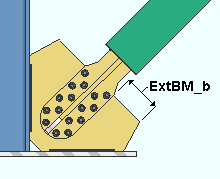
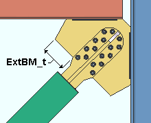
Note 1: When " 90RetBM_b " is ' True ', reducing " ExtBM_b " could reduce the length of the gusset plate along the framing edge (" Lwbr_b "). If " Lwbr_b " minus the weld setback distances (" Lwb left... " and " Lwb right setback") is less than the minimum weld size reported by the " Lwb_b " field, the read-only entry to " Lwbr_b " will be invalid. This also applies to the top connection ( 90RetBM_t ," " ExtBM_t ,"" Lwbr_t ", and " Lwb_b ").
Note 2: When " 90RetBM_b " is ' False ', reducing " ExtBM_b " could reduce the overall length of the gusset plate (" LgbT_b "), which, if less than " Lwbr_b " plus the " Plate Clip " distance, will be invalid. This also applies to the top connection ( 90RetBM_t ," " ExtBM_t ," LgbT_t ," and " Lwbr_t ").
ExCol_b and ExCol_t: The distance (in the primary dimension " Units " or other units ), perpendicular to the member line of the CoreBrace member, from an edge of the CoreBrace member to the non-framing edge of the gusset plate along its width (opposite the edge that welds to a column.)
|
|
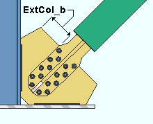
Note 1: When " 90ReCol_b " is ' True ', reducing " ExtCol_b " could reduce the length of the gusset plate along the framing edge (" Lwcr_b "). If " Lwcr_b " minus the weld setback distances (" Lwc left... " and " Lwc right setback") is less than the minimum weld size reported by the " Lwc_b " field, the read-only entry to " Lwcr_b " will be invalid. This also applies to the top connection ( 90RetCol_t ," " ExtCol_t ,"" Lwcr_t ", and " Lwc_b ").
Note 2: When " 90RetCol_b " is ' False ', reducing " ExtCol_b " could reduce the overall length of the gusset plate (" LgcT_b "), which, if less than " Lwcr_b " plus the " Plate Clip " distance, will be invalid. This also applies to the top connection ( 90RetCol_t ," " ExtCol_t ," LgcT_t ," and " Lwcr_t ").
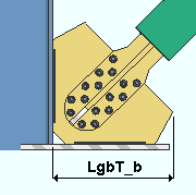
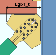
LgbT_b and LgbT_t: A read-only distance (in the primary dimension " Units " or other units ). This is the overall length of the gusset plate, measured perpendicular from its column framing edge to its outermost extent.
|
|
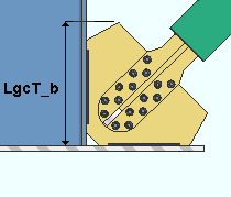
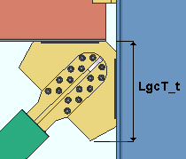
LgcT_b and LgcT_t: A read-only distance (in the primary dimension " Units " or other units ). This is the overall width of the gusset plate, measured perpendicular from its beam or base/cap plate framing edge to its outermost extent.
|
|
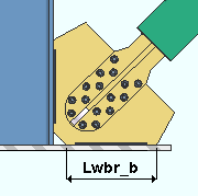
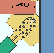
Lwbr_b and Lwbr_t: The length (in the primary dimension " Units " or other units ) of the gusset plate along the framing edge that welds to a beam or a base/cap plate, exclusive of the " Plate Clip " distance. " Lwbr_b " can be adjusted when " 90 RetBM_b " is set to ' False ' and this setting is unlocked ( ![]() ); otherwise, this length is equal to the overall length of the gusset plate (" LgbT_b ") minus the " Plate Clip " distance. (Similarly, for " Lwbr_t, " " 90 RetBM_t, " and " LgbT_t ".)
); otherwise, this length is equal to the overall length of the gusset plate (" LgbT_b ") minus the " Plate Clip " distance. (Similarly, for " Lwbr_t, " " 90 RetBM_t, " and " LgbT_t ".)
|
|
Note 1: If the weld length cannot meet the minimum specified by the " Imported file ," the resulting " LgcT_b " distance will be invalid. This could be the case if you reduce " ExtBM_b ," or if you increase the " Plate Clip " distance.
Note 2: Entering a non-zero " Lwb left... " or " Lwb right setback " reduces the length of the weld. If the resulting weld length doesn't meet the minimum specified by the " Imported file ," the entry to " Lwcr_b " will be invalid.
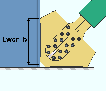
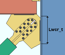
Lwcr_b and Lwcr_t: The length (in the primary dimension " Units " or other units ) of the gusset plate along the framing edge that welds to a column, exclusive of the " Plate Clip " distance. " Lwcr_b " can be adjusted when " 90 RetCol_b " is set to ' False ' and this setting is unlocked ( ![]() ); otherwise, this length is equal to the overall width of the gusset plate (" LgcT_b ") minus the " Plate Clip " distance. (Similarly, for " Lwcr_t, " " 90 RetCol_t, " and " LgcT_t ".)
); otherwise, this length is equal to the overall width of the gusset plate (" LgcT_b ") minus the " Plate Clip " distance. (Similarly, for " Lwcr_t, " " 90 RetCol_t, " and " LgcT_t ".)
|
|
90RetBM_b and 90RetBM_t: True or False .
When ' True ' is selected, the " Lwbr_b " distance is read-only and the option is unlocked (
). In that case, " Lwbr_b " always equals the overall length of the gusset plate (" LgbT_b ") minus the " Plate Clip " distance. (Similarly, for " 90RetBM_t ," " Lwbr_t ," and " LgbT_t .")
When ' False ' is selected, the " Lwbr_b " option can be locked (
) so that you can make an entry to it. (Similarly, for " 90RetBM_t ," and " Lwbr_t .")
90RetCol_b and 90RetCol_t: True or False . When this is set to ' True ', the " Lwcr_b " distance is read-only and will be unlocked ( ![]() ).
).
When ' True ' is selected, the " Lwcr_b " distance is read-only and the option is unlocked (
When ' False ' is selected, the " Lwcr_b " option can be locked (
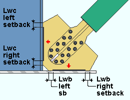
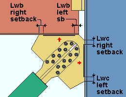
Lwb left setback: The left setback distance (in the primary dimension " Units " or other units or the gage ) of the left gusset to beam or base/cap plate weld.
Lwc left setback: The left setback distance (in the primary dimension " Units " or other units or the gage ) of the left gusset to column weld.
Lwb right setback: The right setback distance (in the primary dimension " Units " or other units or the gage ) of the right gusset to beam or base/cap plate weld.
Lwc right setback: The right setback distance (in the primary dimension " Units " or other units or the gage ) of the right gusset to column weld.
|
The left (or right ) end of a weld on a particular side of a gusset plate is found when you are oriented on that side and are facing (as indicated by the arrow ( ↑ )) the column, beam, or baseplate that the plate is attached to by the weld. |
Note: Increasing weld setback distances could change the value of, for example, the " LgbT_b " or the " Lwbr_b " field, making it invalid. That is because the length along the framing edge of the gusset plate, minus any weld setbacks, must equal at least the minimum weld size reported by the " Lwb_b " field. This applies similarly for column settings (e.g., " Lg c T_b ") and for [ Left End Settings ] (e.g., " LgbT _t ").
Gusset Grade: A36 or A572 or etc. This is the grade of steel for the gusset. This is also the " Steel grade " of the rectangular plate material that each gusset is made of.
Setup: This list box (
) is populated by entries made at Home > Project Settings > Job > Plate Grades .
Stiffener(s) Grade: A36 or A572 or etc. This is the grade of steel for the stiffeners. This is also the " Steel grade " of the rectangular plate material that each stiffener is made of.
Setup: This list box (
Bolt Grade: A325N or A490N or A307 , etc. This is the type of field bolt used for field fastening the buckling-retrained brace to the gusset.
Setup: The choices found on this list box (
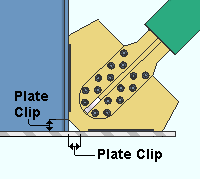
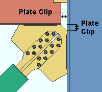
Plate Clip: A distance describing the plate corner clip (in the primary dimension " Units " or other units or the gage ).
|
|
Note: The connection gusset's corner clip size can be adjusted, so long the size meets the weld length minimums set by the " Imported file ."
|
|
------ Graphical ------
These options adjust CoreBrace connection settings. When you add a CoreBrace member, these custom components are added to its ends. The CoreBrace- supplied project-specific text file designs connections for the " Member location " that you choose. You can also, by using the Add CoreBrace Connection tool, add connections to the CoreBrace members.
Graphical : ![]() or
or ![]() .
.
A CoreBrace connection is automatically set to "
Supporting Member: The number of the member supporting the left or right end. By changing this number, you can change the member to which the gusset plate is shop welded, possibly making the brace or other nearby members easier to erect at the construction site.
CoreBrace Disclaimer: Pressing this button opens a dialog box bearing the CoreBrace tool's disclaimer.
![]()
![]()
![]()
![]()
![]()
![]()
![]() ( form buttons ) are named " Copy " " Paste " " Save " and " Load ."
( form buttons ) are named " Copy " " Paste " " Save " and " Load ."
Form buttons that are at the bottom of the window operate on all settings, across the entire edit window. This means, for example, that " Copy " will copy all settings on the window.
Form buttons embedded in the headers for individual leaves apply only to the settings that are contained in that leaf.
Click here for more information about how form buttons work.
"Properties" opens the Edit Properties window, on which you can make entries to custom properties . If, at the time it was created, your current Job was set to use a legacy flavor, the window that opens is named Custom Properties , not Edit Properties .
The Edit Properties window can also be used to read "
Tip: Model > Member > Properties is an alternative to this button. It opens the Edit Properties window without your first having to open a member edit window.
" Status " opens the Member Status Review window, which can give you additional information about the CoreBrace member, and which you can use to enter status information.
"OK" (or the Enter key) closes this window and saves the settings on it.
Red-colored highlighting identifies an entry that is invalid. You need to change that setting, or you will not be able to close this window using " OK ." Solids on "OK": If the appropriate choice is made to User and Site Options > Modeling > " Automatically process after modeling operation ," then the member will automatically be regenerated ( Create Solids will take place) after your press " OK ." Otherwise, you will have to manually Process and Create Solids in order for changes you made on this window to be fully updated in the 3D model.
"Cancel" (or the Esc key) closes this window without changing (or adding) the member you are editing (or adding).
"Reset" undoes any changes made since you first opened this window. That is to say, " Reset " populates this window with the settings that were originally entered to it when you first opened the window. The window remains open.

